
NAD 214 poweramp refurbishment
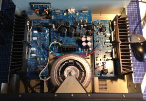
Being an audio enthusiast, a proper power amp can be a thing of beauty. Big toroidal transformers, capacitor banks and relatively easy to understand symmetrical layout. A friend of mine donated his NAD 214 after upgrading to a 200 watt, THX certified, Parasound poweramp.
The NAD wasn’t without fault. It sporadically started producing some noise and hiss. A bit of googling showed some common issues with the 214 (and his bigger brother, the 216). Issues that could be the cause of the noise:
- Bad solder joints
- Oxidized print connectors
- Fried speaker relay
- Undersized/ dried up main PSU capacitors
- Offset idle current

Bad solder joints
The NAD 214/216 are prone to bad solder joints. An explanation might be the rather thin PCB combined with the heating up and cooling down of a typical power amp. The remedy is simple, although it requires some time; resolder all critical joints. Luckily, there’s room to spare inside the housing, but the high-current cabling is soldered directly to the PCB which takes some hassling, but it’s doable.
Oxidized print connectors
Nothing new here. Where two pieces of metal meet, oxidation can degrade a proper connection, resulting in all kinds of strange issued. A small piece of steel wool or fiber optic pen and some kontakt 60 spray can do wonders.
Fried speaker relay
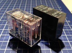
The speaker relay is notorious in the 214/216 series. Over time, either the contacts burn in, or the actual coil burns out. It presents problems ranging from a distorted output signal to the amp being stuck in protective mode. The relay’s housing can be removed so you could clean the contacts, but I’ll take replacement over cleaning any day.
The DEC brand is hard to come by in Holland, but with the help of the spec sheet, I quickly traced a similar relay by Omron. Critical specs are:
- 48V coil voltage
- 4170 ohms coil resistance
- 5A max switching current
- Pin spacing: 7.5mm width, 5x5x5x15mm height
- 2x normally open switch

The Omron G2R-2-48V 48 V/DC 2 matched this perfectly. So, out with the old, in with the new.
Undersized/ dried up main PSU capacitors
The main capacitor bank in the NAD 214 is known to be undersized. The 9400uF (2x 4700uF) per channel can cope with low volumes, but at higher volumes, when more power is needed, bass response can become weak. Electrolytic capacitors dry up over time,  loosing capacitance. This effect is accelerated when used in warm environments. This can lead to distorted audio and other issues.
The NAD 214 uses the same PCB’s as the bigger 216. Because of this, the PSU PCB accounts for 2 additional capacitors (one per channel). These connections can be utilized to increase the capacitance in the 214, without having to resolve to more expensive higher capacitance caps. Also, because board space is limited and higher capacity caps tend to be bigger. So I decided to replace the 4 old 4700 85 degrees with 6 brand new 4700 105 degrees caps. Giving me a total of 14100uF capacitance and better temperature handling.
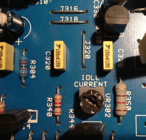
Offset idle current
There is talk about the idle current being set to high for certain production series. The potentiometer used to set the current can change in value as well, so resetting the idle current according to the service manual is always a good idea in the 214’s case.
The service manual’s procedure is as follows:
Ensure VR301 and VR302 are set to minimum (fully counterclockwise) before first switching on.
- Preheat: minimum of five minutes
- Load: no load
- Input: no signal

- Connect DVM (digital voltage meter) across TP301 and TP303, Left channel
- Adjust VR301 left channel for a reading of: 20mV +/- 1.5mV
- Connect DVM across TP302 and TP304, Right channel
- Adjust VR302 right channel for a reading of 20mV +/- 1.5mV
- Leave power on for a further 5 minutes minimum
- Repeat steps 1 to 4
Testing
After all the work, it was time for the fieldtest. I connected my 80 Watt bookshelf speakers, powered up the amp, waited for the click of the brand new relay and listened without any input. Dead silent, perfect. Playing some music, it sounds great. Effortless, defined and powerful. It’s been running for a couple of days without any fault, so it’s safe to say the issues are fixed and the NAD 214 can provide me with music for hopefully many years to come.
48 responses to “NAD 214 poweramp refurbishment”
Trackbacks / Pingbacks
- - March 11, 2013

Thanks for this article. Just refurbished my 214. Piece of cake with this instruction. Works fine again. Next will be the 317 (i only use the power amp part) which will get more or less the same treatment (any extra instructions?).
Bastiaan
Hi Bastiaan,
Awesome it helped you giving the 214 a new lease of life. I’ve never had a 317 on my bench, but the same will apply. Big caps dry out, relays burn in and solderjoints can crack after years of service.
Thijs
The 317 is working great again. 317 uses the same relay as the 214. however less space for the capacitors, but already 6 in place as standard,and the connections from power print to power amp part are soldered, not with connectors. Full system now sound great again. NAD C162 pre amp combined with 214 and 317 as power amps driving B&W 703. 214 doing stereo mid/high, 317 doing stereo low. After refurbishing the way you described fun in listening is back again. Thanks!
Thanks for this article. I have an NAD 314 with similar issues – how would you identify a replacement part or specs for the speaker relay there. The old part is “Type DH2U 24VDC TV-3 DEC 371 Japan” and it has six pins. But this doesn’t seem to be available any more. The service manual doesn’t give any further clues either.
The relay has to meet several criteria in order to work correctly. Pin spacing, working voltage, max current, NO contacts and coil impedance. Sites like Mouser, Farnell, etc. will help in selecting a proper replacement by being able to put in all these variables. The Omron G2R-2-SNDI pops up right away.
The OMI-SH-OMI-SH-248L relay works as well. The only difference is that it has two additional pins for which there are allready holes in the PCB. The coil resistance is 4400 Ohm so that will probably not be an issue.
I found the OMI relay on another website which contained info on NAD 214 repair.
Your capacitor upgrade will be something for the future as well.
Thanks for the suggestion. It’s always good to have alternatives. And the extra coil impedance seems negligible indeed. Good luck with the repairs!
Hello there. How do you get the relay out to replace it? mine seems stuck. I only see one small tap on the back side, which if I were to press it with a screwdriver, I would first have to take out the print board, which will open up a whole new level possible mistakes. Thanks for this guide!
Hi Rune,
The relay has be de-soldered from the backside of the PCB, by removing the screws holding the PCB, and using either some copper solder wick or a desolder pump. Wiggling the relay while heating the contacts can help to pry it out, but be very careful not to lift the solder pads of the board, which is a real risk. Be careful not to use too much heat for too long on the same spot.
Thanks a lot, makes sense. Only hoped that it was an easy plug in-plug out exchange. Will get to the delicate work of desoldering the part of the print board.
The solderpads are very delicate in NAD products of this era it is indeed very important to take great care when doing soldering work inside NAD products.
Mine is doing very good after the relay replacement. I took the old one apart and the contacts were completely black from dirt.
I hope that I don’t have to see the inside of the 214 for a while 🙂
Hi!
Can you remember what caps you used? Im wondering which ones would fit..
Hi Samuli,
I’m afraid I don’t remember the exact capacitors I used. All I do remember is that they were generic. Not in a bad way or anything, but the contact spacing, temperature rating, capacitance, diameter, etc, were very common and easy to come by.
Good luck with the repair!
Thijs
Hi! Thanks for reply and great guide!
Hi thijs,
Nice job.
I want to do the job with mine 214.
Please can you tell me the voltage you used for the 4700uf caps?
Thanks,
Gerben
Hi Gerben,
I used generic 63V capacitors. I believe the originals where 63V as well, so decided to stick with that.
try: KMH Chemi-con, you can see they fit (25mm <-) 4700uF 63V
Thank you both!
Gerben
can you please inform me where you bought these type capacitors ?
The capacitors came from Mouser.com but are also available from Farnell, RS, Digikey et cetera. The exact brand doesn’t really matter, as long as they are proper quality. Please don’t get tricked into buying ‘Audio grade’ or other overly expensive models.
where can I buy the relay
The relay is fairly generic and should be available at various electronics suppliers. I see Mouser, Farnell, RS and TME carry this exact type. I wouldn’t be surprised if your local components selling store can hook you up.
thank you for the information that was very help
If my NAD 214 seems to run fine for a few weeks, but then suddenly puts out a powerful loud hum from both channels, do you think this is the speaker relays? I tried to have it repaired before but problem came back.
Hi Jim, It could be number of things. The speaker relay being one of them. It could also be a problem with the PSU or relay driver for example. Hard to say without having the amp on a test bench. Specially if the fault is that sporadic.
Did you check the connections from the main PCB to the amplifier PCB’s?
My 214 did the same and I removed the two small two pin connectors and soldered the cables directly to the PCB.
You could try to wiggle those connectors to see of it helps.
Hi Remco,
I’m not much of an expert knowing where these connections are. Where approx can I look and how many of them are there?
Thanks! I would love to get this amp fixed. The NAD authorized shop here did nothing.
Hi Jim, I believe Remco is referring to the little white 5 (or 6) pole connectors with black wires coming out of them. If you look at the second photo in my post, the one with the six new capacitors, you can find them in the top left corner. The other side should be mirrored. The contacts can become oxidized. Removing them and giving them a thorough but (really) careful cleaning might solve the issues described.
It’s not the flatcable connector it is the small 2-pole connector with the piece of coaxial wire.
If you look at the first picture off this post you see the wide connector with the flatcable on the top right side of the left board. Just below that there is a small two pin connector. I removed the connector on both the left and right boards and soldered the wires directly to the board.
Followed your instructions and replaced capacitors with 105 deg, and the Omron relay. After the recap work, turned the amp on, everything seems OK, first red light on, then the relay click and green light on, after the recheck idle current, turned the amp on for the second time, but the red light didn’t turn on, after the relay click the green light turned on. Do you have an idea?
Thx
Ales
Hello Ales, to be honest, I’m not quite sure. Since the start up procedure works as expected and the speaker relay kicks in, it seems all criteria are met (DC, temperature and short circuit). Could the the connector to the LED board be oxidized of loose?
Thanks for the guide…. Very useful !
I had trouble with my left channel kept falling out when the amp had run for about 15 minutes. I have soldered a new speaker relay on the PCB and everything seems to work fine… Sound on both channels ! But, if the volume is not set high enough from my receiver, there is no sound on the left speaker. When the volume is turned up, the left channel kicks in again, just like that !!
Do you have any suggestions ? My best guess would be the capacitors, but I nave no experience with this at all…..
Regards D. Helverskov
I doubt it has to do with the capacitors. At least the ones described in the article. The only time I experienced something similar, although not with a NAD 214, but similar, it had to do with a transistor in the differential stage. This stage prepares the signal for the output-power-transistor. But without any measurements it’s impossible to say for sure which one (or even if) is faulty. How does the left channel sound when it does produce sound? Do you hear any distortion? Does it always turn on with the same volume setting? And when it turns on, does it stay on, no matter the volume level?
Thanks for your reply…
When there comes like a loud noise, when watching movies, the sounds pop in…. and then often stays in. But not always, and when the sound disappears, there is just silence. Just the way it was before I changed to an new omron relay. (There were noise with the wearn up relay).
I have checked all cables, and even replaced them. So i know it is the left channel coming out from the speaker, that is the issue.
Regards
I’m sad to say I can’t help you at this point. Without being able to perform any measurements, it’s impossible to say where the problem originates and what components to replace.
I’d check the soft clipping switch. In my 214, when a channel disappeared, I wiggled the switch back and forth until the sound came back and did not drop out anymore. Now this hasn’t happened for a while, but if I get to fixing things inside the amplifier, I’ll see if I can replace the switch.
These amplifiers are very poor quality line signal conductors. those that carried the signal from the connectors to the boards of the left and right channels. In his amplifier I have them replaced at audionote cables. The main reason for the replacement of these wires was that slight crackling could be heard from the speakers.
Great article.
I fitted a 317 and a 214 with new caps and relay and they sound great.
I have used 25mm 6800uf 63v 85C caps from United chem-con insted of the 4700uf ones (part#: ESMH630VSN682MQ50T from farnell), to get some extra uf out of the powersupply.
When I compare the two 214s against each other (with and without the mod) the difference inn sound is enormous. The modified powersupply clearly helps. Also on lower volumes. But when i crank up the power the difference is even more noticable. The extra power gives the music a bigger range of dynamics that makes it sound more open and fun to listen to.
Just finished restoring a 214. I added the two extra main filter caps, replaced the relay and set idling current. The soldering on my unit was fine. I used Epcos filter caps and Nichicon PW and CS for everything else. The 217 sounds better than my vintage Yamaha M4 – smoother with better soundstage. It is driving a pair of KEF Q900 towers.
Nice restore! Good to hear it’s still performing as the great amp it is.
I was inspired to upgrade my 214 after reading this post even though it didn’t have any issues. Thank you! I love this amp. Replaced the relay and 4 caps with 6 x 6800uF’s. I figured why not, it was $10 more. Here are the part numbers from DigiKey I used.
PART: G2R-2-DC48-ND
MFG: Omron Electronics Inc-EMC Div G2R-2-DC48
DESC: RELAY GENPURPOSE DPDT 5A 48V
PART: 565-2695-ND
MFG: UnitedChemi-Con ESMH630VSN682MQ50T
DESC: CAP ALUM 6800UF 63V SNAP
NAD Service Manual for the 214 / 216 (PDF) https://anonymousfiles.io/QiOOhPEW/
(files are virus scanned by the service)
I’m glad I found that blog!
I tried to offset idle current, but I cannot, cause the value is slowly increasing over time ?????
Cool! Did you allow the amplifier to warm up before adjusting the idle current?
Thanks. I could do it now . But I have to wait at least 10 min until value stabilizes.
Power consumption immediately after start is about 30 W. After 10 min at about 50 W. No consumer 🙂
Is this normal??
Thanks Thijs, for this blogpost. My NAD 317 is quite fresh and nice again!
The NAD 317 has one additional relay (“RL501”):
Do you or your blog-readers has an idea how to replace the “Takamisawa 5MB-NR 5VDC TV-8” (VS-5MB TV810a) relay?
Coil Voltage is 5 VDC and Coil resistance is 36 ohm. On the case of the relay there’s: “15A,250V~AC, 15A/120A 250V ~AC/0860”
I searched the “whole internet” but wasn’t able to find a replacement part. (maybe I searched for the wrong key specs??)
Thanks in advance for any support!
Hi Georg! Nice te hear another one has had the care it deserves :). Regarding the relay. Two factors are critical in my opinion. The 5VDC for the coil and the footprint to solder it to the PCB with the correct pin order. The rest of the specs aren’t a 100% critical in my opinion. The coil resistance can vary by e.g. 10%, the 15A rating can be 14A or higher (16A, 25A, etc.) as well. Have a look at the Omron GR5L series for example.
Thanks, that helped!
I found two promising ones, but with doubled coil resistance (“FTR-K1 5V” and “G5RL-1E-HR 5DC”). I ordered both and will check if it works… but I don’t thinks so 🙂
At the end I have to clean the old one. I will report…